Research Cell
Mechanical and Electronics Related Information and DIY Projects
7809 is a voltage regulator integrated circuit (IC) which is widely used in electronic circuits. Although we can build our voltage regulator circuits using the components available on the market it will take a lot of time to assemble those parts on a PCB. Secondly, the cost of those parts easily exceeds the price of LM7809 itself so professionals usually prefer to use 7809 IC.

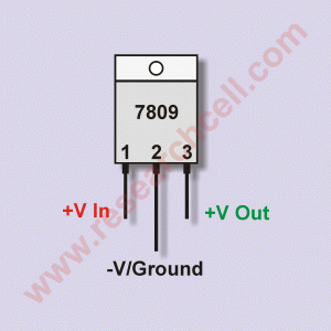
Before you start using 7809, you will need to know about the pin structure of IC 7809. It looks like a transistor. It has three pins. For a better understanding, I have given an image of 7809 below. Please take a look.
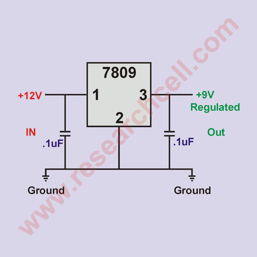
You can easily see the V in and V out pins as well as the ground pin. It is really easy to use 7809 for voltage regulation purposes. I have also included a circuit diagram of 7809 so that you may learn how to use it in a circuit diagram.
It is wise to use two .1uF capacitors on both input and output sides to filter any ripple or distortion in voltage but it is not necessary.

In the image, you can see that 12V is being supplied on the input side of 7809 but the output side of 7809 is outputting Regulated 9V. As long as the input voltage remains above 9V, the output voltage of 7809 will remain smooth and regulated.
Please note that an input voltage of 7809 can be up to 23V but in my experience, it is wise to avoid input over 15V. 7809 is claimed to output 9V and almost 1.5A Current but again, I have experienced that we should not put a load over 9V and 1A on it. Since we are using it in the power supply, the transfer of power will result in heat output. We will need to use a heat sink with 7809 otherwise this heat can damage it. It is advised to use a 1A fuse on the output side of 7809 and a 1.5A fuse on the input side of 7809 to avoid damage in case of a short circuit.
Hello,
Do you a kit or circuit board that I can order
Thanks,
Nolito
Thanks for the 7809 pinout information. Your diagrams really helped me in understanding 7809 pinout. Can you please tell me if 7812 also has same pinout configuration?
Thanks. Diagrams helped me very much.
sir how can i increase my inverter voltage.send the description of the transformer i will use form 1000w inverter in my mail
what is the function of capacitor in this circuit
Thanks for you diagram on the 7809 IC, it has helped me in my project work. I am also having some Challenges concerning the tuning my inverter. I am having a a very high frequency around 11.o5 MHz, I was expecting 50Hz please how do i go by it. The inverter is a 500W inverter diagram on http://www.reserchcell.com. Pleas help me out
hello
here you regulate the dc supply
if i want to regulate the ac power than
what will be the modification in the circuit ?
as i read this post i think it can help me a lot. where do i put the fuse, in series with the positive voltage before or after the capacitor?
For the question regarding the use of capacitors with the LM78XX (LM7809 in this case): The capacitors are used as a filter and stablizer for more consistant input and output of the regulator. It is suggested in virtually all applications and, is recommended by most LM78XX manufacturers. As stated in the opening of this page, it can be used without the capacitors in applications were consistancy is not requirement, such as running low draw fans or incandescent bulbs that can handle fluxuations.
thanks for you diagram on 7809 IC.it has helped me my work.
Genius, thanks a lot for your cct diagram ,and all the Details, i wonder why people complain,i copied mine from my x2-01 Nokia set, and its very clear.
Sir thanks for 7809 dirgram. pls can u send me names of d working materials like i.c, resistor, diode etc. pls thanks
Thank you very much! A man like me who never made any such thing managed to connect my D-battery powered radio to a 12V truck battery at first attempt. Simple and easy, much appreciated.
its is so helpful information.
it is very simple ckt but when power will come how it will work and how battery gets charge ,kindly clear .i want to use in main line to use it when ever power goes it should be automaic on and whenever comes it should be off.
thanks
sushil verma
this info. really helped me in making my project