Research Cell
Mechanical and Electronics Related Information and DIY Projects
LM 7905 is a standalone 5V voltage regulator integrated circuit with negative output polarity therefore it is used in such power applications where a positive ground voltage is used instead of a negative. 7905 is an extremely easy-to-use IC and has only 3 pins.
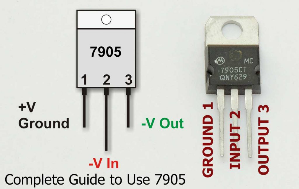
It has a transistor-like TO-220 shape which makes it easy to fit on any PCB or ready-made heatsink plate. If you grab an LM7905 from its legs facing the number with the correct orientation, the left pin will be its Ground pin, the center pin will be input and the right pin will act as the output pin.
7905 can even function without any capacitors at its input and output though I recommend 4 adding them for a smoother output. 7905 belongs to the linear voltage regulators family so although it is very stable and easy to install at the same time it will waste a lot of energy in the form of heat. This wasted energy is directly linked to the input voltages of 7905, the higher the input voltages, the more energy it will waste as heat.
Here is the image showing the basic usage of 7905 IC:
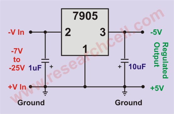
You can see that a 1uf capacitor is used at the input to filter the noise. Make sure that the capacitor voltage is more than the input voltage. Another 10uf capacitor is used at the output to further refine the output current. Input voltage can be anywhere between 7v to 25V. If you have a small load then you won’t need a heatsink plate. However, for 1A or above loads, you should attach a heatsink plate. The maximum allowed current is 1.5A.
7905 has built-in overcurrent and short circuit protection features. These features can kick in once the maximum allowed current is reached. It also has a documented thermal protection against overheating but beware that operating the IC near its maximum temperature can potentially alter its dye structure resulting in unpredictable behaviors. I certainly don’t recommend you to put a continuous load of 1.5A on it for a long time, instead if you have a bigger load, you should probably look into the parallel use of 7905.
Although it is not officially mentioned anywhere, in reality, I have successfully used two or more 7905 in parallel. Theoretically, no two 7905 can give the same output voltage, so the one which gives more voltage will try to take more load and will be throttled later putting all the load to the other one which will then be throttled too. This can result in a never-ending loop but we can overcome this by adding a low-value but high-power resistor at the end of each voltage regulator.
This will counter correct the small voltage differences between both regulators and will more evenly balance the current between them. Technically we can get close to 3A current from two 7905 ICs if attached as shown in the image. A small amount of current is wasted as heat in the resistors but it’s not very noticeable.
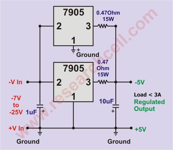
Please note that in our circuit, we soldered both 7905 very close to one another. Therefore only two capacitors are used at the combined input and output of both regulators. Please try to fit the regulators as close as possible, in case of 3 inches or more gap, please use an individual capacitor for each regulator IC.