Research Cell
Mechanical and Electronics Related Information and DIY Projects
LM317 is a famous linear voltage regulator IC. It provides a very stable, uniform, and smooth output which does not fluctuate with load changes. It can also be used as a precise current limiting device which is essential for testing electronic equipment.
Unlike the 78xx series, the output voltage of LM317 can be adjusted using a variable resistor or a set of fixed resistors. It has built-in short circuit protection as well as thermal overheat protection.
LM317 is exceptionally easy to use and requires only two resistors to do basic voltage regulation however more refined output can be achieved using a few more components. No capacitors are needed unless the input source is situated far enough from LM317.
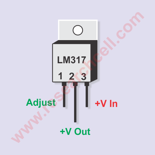
LM317 has 3 pins and a transistor-like TO-220 shape which makes it easier to fit on heatsinks. If you grab LM317 upside down while IC’s printed name is facing towards you and its pins are on top, then the left pin is the input pin, the center pin is the output pin and the right pin is the adjustment pin.
Note: The heat exchanger or heatsink plate also acts as an output terminal due to its internal connection with the center pin. I have also added an image to make sure you fully understand the pin numbers for LM317.

LM317 has a wide input range of 4.25 Volts to 40 Volts while the output range is between 1.25 Volts to 37 Volts. The minimum possible difference between the input and output voltage is 3V, anything below that and output may start to fluctuate unpredictably. The maximum possible voltage differential is 40V.
With a decent-sized heatsink, LM317 can output up to 1.5A (1500mA) of current however you will have to make sure the maximum operating temperature of LM317 doesn’t exceed 125C otherwise it will thermally shutdown or can even get permanently damaged.
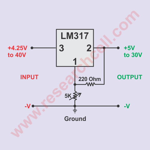
I am adding a circuit diagram of a very basic voltage regulator circuit using LM317 which is extremely simple and it can even be built without a PCB or breadboard. You can fit lm317 upside down on a heatsink and solder the resistor directly on the top of its pins. The variable resistor can be connected to the LM317 using wires and can be placed anywhere you want.
If you are fitting this circuit inside a box then you should drill a hole in front of your box and place the variable resistor in that hole with a plastic nob outside to adjust the regulated output voltage.

You can also replace a variable resistor with a fixed resistor in case you need fixed output voltage. For example, you can get a 5.1V DC output from this circuit if you replace the 5K variable resistor with a fixed 680 OHM resistor. You can use the following formula to calculate which resistors to use and what output voltage you will get.
Vout = 1.25 X (1 + (R2 / R1) )
In case of 680 OHM, this is how we calculate expected output voltage
=1.25 X (1 + (680 / 220))
=1.25 X (1+ 3.09)
=1.25 X 4.09
Vout=5.1V approx.
Note: Value of R1 and R2 should be in OHMs
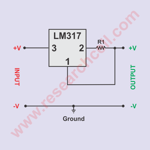
In the image below you can see a very precise yet very simple circuit that limits current to a value determined by an R1 resistor. I have found this circuit surprisingly accurate and even comparable to some pretty professional current limiting power supplies.
Please note that LM317 itself is pretty accurate however the R1 resistor should be big enough to not heat too much otherwise the heat may result in changing the value of resistance slightly which will result in changing the current by a few milliamps.

For example, a 3.9OHM resistor in place or R1 will output approximately 320 milliamperes current regardless of the voltage you set.
You can use the following formula to calculate the output current.
Output Current = 1.25 / R1
Note: Value of R1 should be in OHMs
Yes, but just for very light loads and you will also need to monitor the operating temperature of LM317 so that It does not exceed 125C.
In my experience, if your application has a heat dissipation of less than 1W then there is a good chance that you can use the IC without a heatsink plate. However please note that continuous use of LM317 near its maximum operating temperature can alter its die and reduce its life span.
5V DC power supply is the one of the most common DC power supplies. Although LM317 can also give you a regulated 5V output but if you need to power a 5V circuit then LM7805 is a better choice since you dont need to use the extra resistors to set the voltage. Also LM317 will need a fine tuning to get exact 5V where as LM7805 is specifically built to give exact 5V output. If you want to know more about LM7805 then you should visit the following link.
How to use LM7805 Voltage Regulator
If you are planning to use LM317 in your circuit and you have any questions in your mind then please don’t hesitate to post them in the comments section below.