Research Cell
Mechanical and Electronics Related Information and DIY Projects
LM 7912 belongs to the 79xx family of voltage regulator ICs and is very commonly used in such power supplies where 12V negative voltage output is required. 7912 is almost a standalone regulator IC. The reason why I used the word ‘almost’ is because although it is recommended to use a 1uf capacitor at the output of 7912 to refine its output yet it can still be used without an output capacitor in non-sensitive circuits.
The TO-220 shape makes it an easy to attach components with existing heatsink plates. However please note that an isolation washer is almost always used with TO-220 packages to avoid short circuits with heatsink plates.
If you grab 7912 from its pins with its number facing you and the heatsink on the top then the left-most pin will be the ground or +V pin. The center pin is the input pin or -V pin and the right-most pin is the output pin. We count PINs from left to right so the left pin is PIN 1; the center pin is PIN 2 and the right pin is PIN 3.
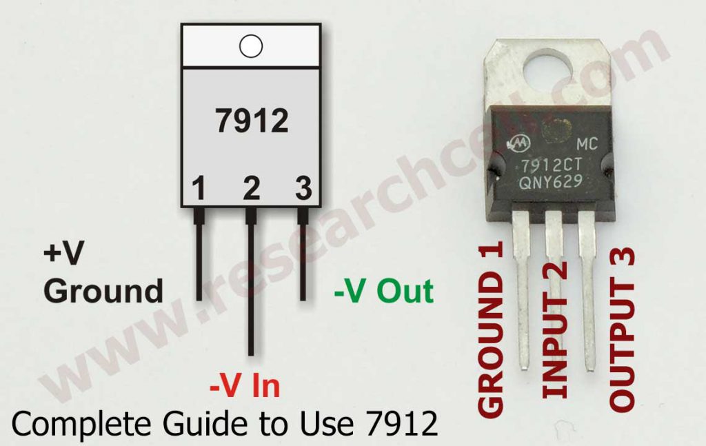
| Pin 1 | Pin 2 | Pin 3 |
| Ground, +V | Input, -V | Output (Regulated Negative Output) |
Now I am going to show you a couple of simple circuits we can make using 7912 and I will also tell you about its important features. The circuits I am sharing are very simple and you don’t need to have advanced knowledge of electronics.
I am adding an image on this page that shows the most basic circuit diagram using 7912 for voltage regulation purposes.
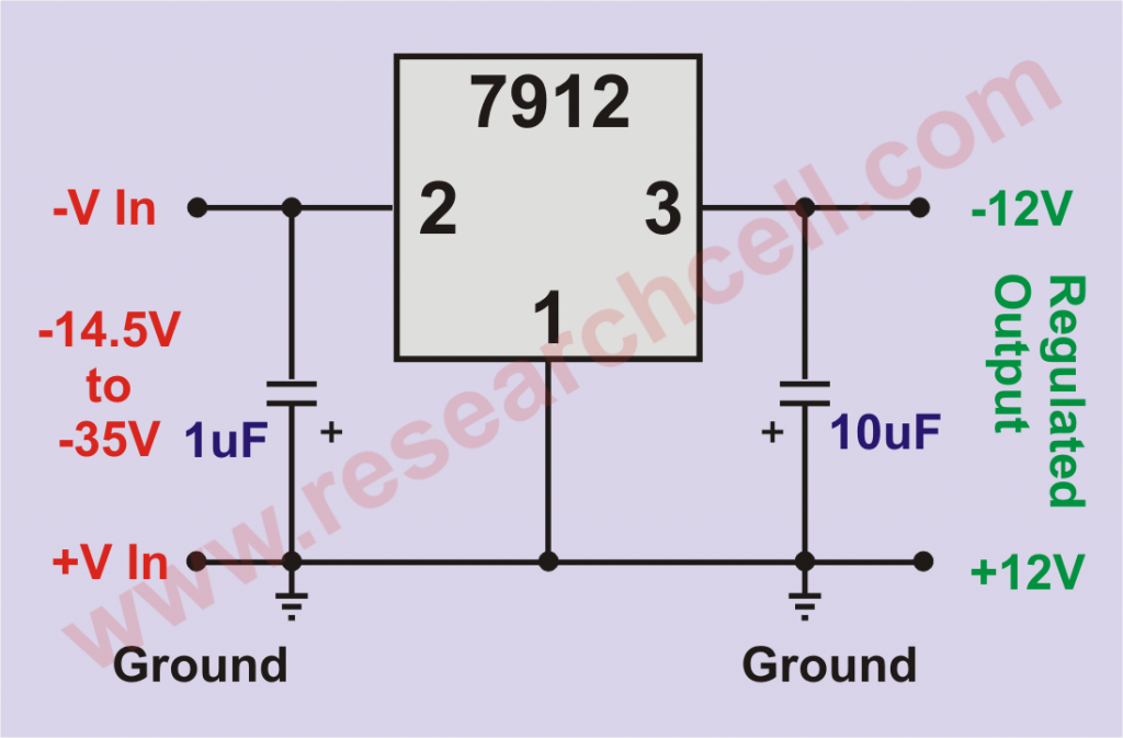
As you can see, apart from 7912, only two bypass capacitors are used. These capacitors should be placed as close to 7912 as possible. You can omit the input capacitor if 7912 is placed within 3 inches of the main supply capacitor but the output capacitor is highly recommended to avoid distortion in the output voltage. The input capacitor is 10uf/50v and the output capacitor is rated at 1uf / 50V but you can use a film capacitor of 105PF rating as well here.
The input range for LM 7912 is from a minimum of 14.5V to 35V maximum. Since you are going to input raw voltage to LM 7912 you should first stress test your power supply by putting a 1.5A load on it to see how low the voltage goes. Your power supply voltage should not drop below 14.5V to get a fully regulated -12V output from 7912 IC. Also, make sure to check your power supply’s unloaded voltage. They should not exceed 35V otherwise they can burn the IC.
Theoretically, you can put up to 1.5A of continuous load on 7912 but in my experience, it works best with loads up to 1A after which it tends to heat up and sometimes causes issues due to built-in thermal protection.
Also, you need to keep an eye on all the heat it dissipates. If you are keeping your circuit inside a small container then it can make it very hot. This heat buildup can exceed the safe operating temperature of other components in that container.
A 7912 at full load can drop up to (4%) half a volt which can be critical for sensitive circuits. If your load is continuously at 1.5A or a bit above then you should consider using more than one 7912 in parallel.
Being a linear voltage regulator, 7912 is not very efficient and it wastes a lot of energy as heat. The more the gap between input and output voltage, the more energy it will waste by generating heat. You can use the following formula to calculate how much energy is being wasted as heat.
(Input Voltage – 12) x Output Current
If you are using a 24V power supply as an input source for your 7912 and your load is pulling 1 Amp from the 7912 then the following is how we will calculate the energy being wasted.
(24 – 12) x 1
=12 x 1
=12W
You can see that you will be wasting an additional 12W as heat energy by using 12W for your source. In addition to this loss of energy, you will also need to dissipate that heat using a large heatsink plate. To avoid this issue, 7912 input voltage should stay as close to 14.5V as possible but at the same time the input voltage should never drop below 14.5V otherwise the output will become unregulated. I recommend using an 18V power source for this purpose.
Theoretically, no two 7912 can deliver the same output voltage due to the micro differences in their dies from the manufacturing process. The voltage difference is usually only a few millivolts that can be covered by slight load balancing. To achieve this, we can use resistors. I have added a circuit diagram in which we are using two LM 7912 in parallel to achieve an output close to 3A. In case of continuous load, you can comfortably put 2A to 2.5A load on it which can even spike to 3A for small intervals.
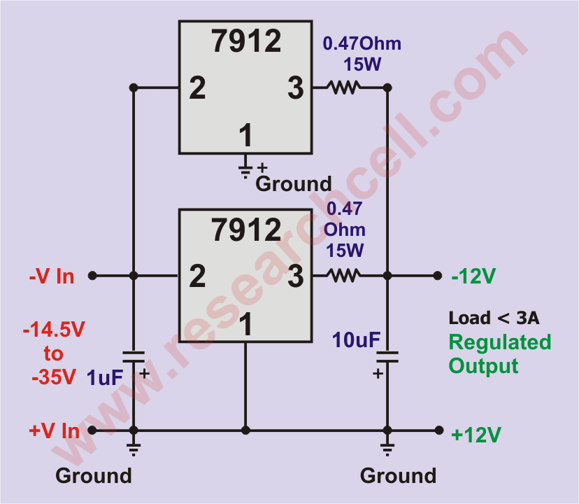
This circuit is pretty much self-explanatory, we have two 7912 in parallel with a 0.47Ohm resistor attached to the output of each 7912. Please note that both of these resistors must be at least 15W otherwise they will burn at the peak load. At the combined input and output, we have two capacitors of 10uf / 50V and 1uf / 50V respectively.
LM 7912 has inbuilt overload and short circuit protection, and safe area protection, and on top of that, it also has a thermal shutdown so it is a great safety package. These features are certainly essential to protect the devices you are powering with your 7912.
If you have any questions then please feel free to ask in the comments section below.