Research Cell
Mechanical and Electronics Related Information and DIY Projects
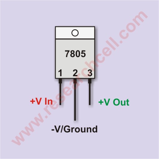
7805 is an easy-to-use linear voltage regulator IC which outputs 5 volts rated at max 1A. It takes an unregulated voltage input and converts this fluctuating voltage input into a perfectly regulated smooth 5 volts power output. For example, a 12-volt lead acid battery when fully charged gives out approximately 12.70 volts and when fully discharged, it gives out 10.50 volts. This difference can be even more under a variable load. If we use this battery as an input source for our 7805 then the output voltage will remain 5 regardless of that voltage difference during the charging and discharging phases.
I have attached an image of 7805 IC to describe its pin configuration setting. In addition to that I have also attached a small fully working voltage regulator circuit diagram with this tutorial.
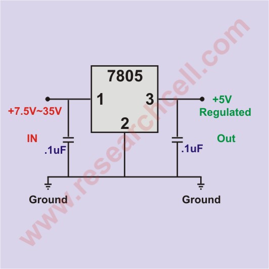
The two capacitors used in the voltage regulator circuit are not mandatory but they are good to maximize voltage regulation. The capacitor values I have used in this circuit are not written on stone, you can change them slightly.
7805 IC has a thermal shutdown feature to protect the IC in case of overheating so it should be safe to use 7805 without a heatsink plate for less than 200mA load. However should your load cross 200mA, you should consider using a heatsink plate. The heatsink plate should be large enough to bring 7805 heat to such a level that you can comfortably touch it.
7805 is a linear voltage regulator, so it is not very efficient and it has a drop-out voltage problem. It wastes a lot of energy in the form of heat. You can calculate the wasted energy with the following formula. This formula will also help you to estimate the size of the heatsink plate you will require to disperse the amount of heat generated by 7805.
(Input Voltage – 5) x Output Current
Suppose the input 15 volt and output current you require is .5 Amp by using the above formula
(15 – 5) x 0.5
=10×0.5
=5W
5W energy is being wasted as heat and you will need a decent-sized heatsink plate to disperse this heat to ease your 7805. On the other hand, the energy you are using is only (5 x 0.5Amp) =2.5W. So you are going to waste twice the energy you are utilizing. On the other hand, if give your 7805 9V as input at the same amount of load, only 2W { (9-5) x 0.5 } energy will be wasted as heat.
So the conclusion is, that the higher the input voltage gets, the less efficient your 7805 will be.
You should try to stay slightly over 7.5V. However, don’t get below 7.5V as your 7805 won’t give a regulated output if the input voltage gets below 7.5V. If your input voltage is less than 7.5 like 6V then you should consider using a low dropout voltage regulator such as LM2940. Pin connections of LM2940 are also the same as 7805.
You don’t need extra components to create a 5-volt regulated power supply with 7805. However it is a good idea to use one capacitor on the input and one on the output pins to make output voltage smooth but then again, they are not necessary to be used. As per specs, 7805 input voltage should range between 7.5V to 35V but I haven’t tried more than 15V yet. The maximum output current of 7805 is 1A with a good-sized heatsink plate.
Please note that LM7805 is not designed to be used in parallel that is because no two LM7805 can output the same voltage. One of them may output 4.99V while the other will output 5.01V. Due to higher voltage, the latter will try to take more load than the first one. Also, another issue is the higher voltage IC (5.01V) will try to push the low voltage IC above its maximum volts (4.99V). The lower voltage IC will sense the voltage higher than its upper limit and will shut down putting all the load on the higher voltage IC. It will then power up again once the volt drop as the higher voltage IC won’t be able to take all the load but still this can start an undesirable oscillation especially if the voltage difference is significant.
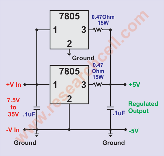
The above circuit is an attempt to balance the slight voltage difference between both regulator ICs using two resistors. As soon as a load is applied to this circuit, the load will push the volts after the resistor to slightly less than 5 which will stop any oscillation caused by voltage difference and will also balance the load a bit more evenly. This way you may be able to extract slightly less than 2A current with the price of a very slight voltage drop below 5V in the final output. Although I have never come across any issue while using this circuit but still I do not recommend you to use it to power up expensive devices.
I have also made a video tutorial on the use of LM7805. Please make sure to subscribe to my channel “Research Cell Videos” on YouTube to keep watching similar and interesting videos.
Just like 7805, 7905 is also a voltage regulator IC that gives regulated 5V output but it is quite opposite of 7805 because it gives out negative output while 7805 gives out positive output. So if the circuit you are going to power has a positive ground or common wire then you should use 7905 instead. You can click on the link below to learn more about 7905.